Supplies
- 6 volt battery
- L brackets (4 big and 2 small)
- 14 gauge single strand wire (50-100ft)
- Iron rod
- Cork
- Spool of thread
- Heavy duty duck tape
- Wood (for base)
- Masking tape
- Hacksaw
- 24 gauge magnet wire
- Scrap wood
- Drill + nails
- 2 Penny Nails
- 16 gauge lamp wire
- 2 wide L brackets
- Boxcutter
Not all of the supplies used are pictures above.
Steps
How to Build Each Part
Base
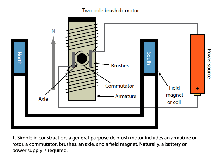
For the base I used a 1'x1' piece of wood. Then I set up two of my big L brackets in the middle of opposite sides and used tape to stabilize them while I drilled them in place. To the base I attached all of the parts (stator and brush bases) using heavy duty duck tape.
Armature
For the armature I connected to penny nails with tape and marked the middle, and then put the iron rod through the space between them. Using a hole i drilled in some scrap wood I positioned the rod upright in order to assist me in the wrapping of the wire. To hold the armature in place I wrapped masking tape around the rod on both sides of the armature. I removed one side of tape (from when I taped the nails together) and began wrapping the 24 gauge magnet wire around leaving extra wire when I started and when i ended. Following this, I scraped off the enamel from the two ends of the wire. To test my magnetic field, I attached the two ends of the wire to the battery (the small sparks were a good sign) and checked to see if a paper clip would stick well to the armature.
Commutator
For this, I attached a cork on my rod by pushing the rod through the cork (with some help from Achilles because I am very weak). Then I held both end of the magnet wire on the cork and place a piece of foil of both wires and taped the foil to the cork to hold it in place.
Stator
In order to make this I used the 14 gauge single strand wire and wrapped it around the other two L brackets, which were taped together. I wrapped the wire five times with a layer of duct tape in between each layer of wire.
Brushes
For the brushes I used 16 gauge lamp wire. I drilled each of the wide L brackets onto a base made of three layers of wood in order for it to line up nicely with the commutator. I did my best to put the brushes in a straight line along the edge of the commutator and made sure that they were touching to prevent any breaks in the circuit.
Connecting It All Together
After everything was on the base/rod correctly, I attached the wires to their proper places. One end of the 14 gauge single strand wire connected to one of the wide metal L brackets of the brushes and the the other end connected to the battery. Then a piece of 24 gauge magnet wire connected from the battery to the other brush.
Complications with My Motor
I was unaware we were given a sheet with directions in class (thanks Achilles) so at first I had trouble understanding the logistics of the motor and how I was suppose to build it. After some research and a lot of trial and error I was able to successfully figure out the process. A few problems that arose included the stator and how it was built. When building my base, I did not account for the extra height the wire would add to the the initial L brackets of the stator so once it was built it was too high for my rod. This was easily fixed by attaching the small L brackets (with a screw and duck tape) to the ends of the L brackets that held my rod. This put the everything on the same level. Another problem I discovered later on was that there was too much distance between my armature and the L brackets of the stator. I tried to fix this by adding a few super magnets to the ends of both sides of the L brackets. But then I decided to just rebuild my stator. Aside from my stator, I, at first, had trouble with the height of my wide L brackets (used for the brushes) as well as the length of my iron rod. To solve these two problems my brother and I bought a hacksaw. It was a mini hacksaw for four dollars, but it was easily the best investment of the project. I used the hacksaw to cut the iron rod into a size fit for my motor. Then, I used it to cut multiple pieces of scrap wood (with I still thankfully kept from the mousetrap project) which was used to make a base for the brushes.
Overall, I do not think the motor was a hard project. It merely took understanding and precision.
Before I remembered I have scrap wood from a previous project, Achilles and I got creative with our bases. (pictured: Achilles using a book as a make shift base)
Here we see our trusty hacksaw cutting our iron rod into a more desired length.
Once again we see the hacksaw cutting scrap wood into pieces to be used.
UPDATE: Based on my motor's performance yesterday there seemed to be more complications that I did not account for.


